A boiler pump is the quiet circulator behind many comfortable homes and commercial heating systems. It moves heated water from the boiler to radiators, underfloor loops, or hot-water cylinders. Without steady circulation, one room may feel warm while another remains noticeably cold. Boiler pumps create the pressure needed to overcome pipe resistance, bends, valves, and height differences.
Inside the pump, an electric motor turns an impeller. The impeller draws water through the inlet and pushes it toward the heating circuit. This process repeats while the thermostat calls for heat. Modern boiler pumps often adjust their speed automatically. They respond to changing demand, helping reduce electricity use and operating noise. Older fixed-speed models may run harder than necessary.
In practical service work, pump problems can appear simple but prove difficult to diagnose. A humming sound does not always mean the pump has failed. Air, closed valves, sludge, incorrect settings, or low system pressure can create similar symptoms. That assumption is often wrong. Checking flow temperature, return temperature, pressure, and pump indicators provides better evidence. Manufacturer instructions should guide every adjustment, especially in sealed systems. A qualified heating professional should inspect electrical connections and internal faults. Never guess with hot, pressurized equipment. This guide explains how boiler pumps work, where they fit within a heating system, and which warning signs deserve attention. It also considers efficiency, common installation mistakes, and the limits of quick fixes. Some systems behave differently. That matters. Understanding those differences can prevent unnecessary replacement and support safer, more reliable heating performance.
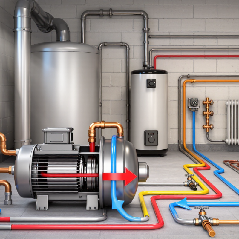
A boiler pump is a mechanical device that circulates heated water through a building’s heating system. It moves water from the boiler to radiators, underfloor circuits, or air-handling units. The cooler return water then flows back to the boiler for reheating. Without steady circulation, some rooms may stay cold while the boiler works harder.
Most boiler pumps contain an electric motor, an impeller, a housing, and control connections. When the motor turns, the impeller pushes water through the sealed pipe network. Modern systems may adjust pump speed according to heating demand. This can reduce electrical use and limit unnecessary pipe noise. The pump does not create heat. It distributes heat.
A technician checking a pump usually listens for grinding, buzzing, or repeated starting. That sound matters. Air trapped inside the system can cause vibration and weak circulation. Dirty strainers, closed valves, incorrect pressure, or worn bearings may create similar symptoms. The fault is not always the pump itself. This is where diagnosis can become less tidy. Measuring flow, system pressure, electrical supply, and temperature difference gives better evidence than guessing. A practical inspection should also check for leaks around seals and confirm that isolation valves are fully open. Small mistakes during installation, such as reversed flow direction, can reduce performance. Regular servicing helps, but maintenance intervals depend on water quality, operating temperature, and system design.
A boiler pump circulates heated water through pipes, radiators, or underfloor loops. It does not create heat. The boiler raises the water temperature, while the pump creates the pressure difference that moves it. Inside the pump, an impeller spins and transfers energy to the water. Warm water leaves the boiler. Cooler return water comes back for reheating.
This movement depends on flow rate, pipe resistance, and system pressure. A variable-speed pump can reduce speed when heating demand falls. The U.S. Department of Energy’s Pumping System Assessment Tool highlights how lower flow can reduce pumping power sharply. This matters because pump power follows the affinity laws, not simple linear savings. The International Energy Agency reported that buildings used about 30% of global final energy in 2022. Small efficiency gains still deserve attention.
Real systems are less tidy. Air pockets can cause noise, weak circulation, or cold radiators. A pump that is too large may cycle, waste electricity, and create rushing sounds. A pump that is too small may leave distant rooms cold. I have seen temperature complaints blamed on the boiler, when the real fault was poor balancing or a blocked strainer. CIBSE guidance stresses correct hydraulic design, balancing, and commissioning. Yet field adjustments are often rushed. Checking pump speed, supply temperature, return temperature, and differential pressure gives technicians useful evidence before replacing equipment.
| Data Dimension | Typical Information | How It Relates to Boiler-Pump Operation |
|---|---|---|
| Primary purpose | Circulates heated water through the boiler, pipes, radiators, fan-coil units, or radiant-floor circuits. | The pump creates a pressure difference that keeps water moving around the closed hydronic loop. |
| Main pump components | Electric motor, impeller, pump housing, shaft or rotor, bearings, seals, electrical connections, and control interface. | The motor turns the impeller, and the impeller transfers mechanical energy to the water. |
| Pump operating principle | Most hydronic boiler pumps are centrifugal pumps. | Water enters near the impeller center and is pushed outward, producing flow and pump head. |
| Heat-transfer medium | Water is most common; water mixed with glycol may be used where freeze protection is required. | Glycol mixtures are more viscous than water, so the pump may require additional capacity to maintain the intended flow. |
| Typical residential flow range | Approximately 2–15 gallons per minute (7.6–56.8 liters per minute), depending on system output and design. | Required flow is determined by the heat load and the temperature difference between supply and return water. |
| Common residential pump head | Often about 4–25 feet of water column, or approximately 1.2–7.6 meters, depending on piping resistance. | Pump head represents the pressure needed to overcome friction in pipes, fittings, valves, heat emitters, and other components. |
| Typical hydronic temperature | Many hot-water systems operate roughly between 120°F and 180°F (49°C and 82°C), depending on system design. | The pump must be rated for the system temperature and fluid conditions. The actual temperature should follow the boiler and heating-system design. |
| Supply-water path | Boiler outlet to distribution piping and heat emitters. | The pump sends heated water toward radiators, baseboards, air handlers, or radiant circuits. |
| Return-water path | Heat emitters back to the boiler inlet or return manifold. | After releasing heat indoors, the cooler water returns to be reheated and circulated again. |
| Heat-output and flow relationship | For water, a commonly used approximation is: Heat output (Btu/h) = 500 × flow (gpm) × temperature difference (°F). | For a 20°F temperature difference, a 100,000 Btu/h load requires approximately 10 gallons per minute of water flow. |
| Fixed-speed pump | Operates at one selected motor speed, usually controlled by a relay, thermostat, or aquastat. | It is simple and reliable, but it may use more electricity or produce more flow than necessary during partial-load conditions. |
| Variable-speed pump | Automatically adjusts speed according to system pressure, temperature, or zone demand. | Lower speed during light demand can reduce electrical consumption and help limit flow noise. |
| Pump control sequence | A thermostat or system controller calls for heat, starts the pump, and enables boiler operation according to the control logic. | The pump may continue running briefly after the burner stops to remove residual heat, depending on the control strategy. |
| Air removal requirement | The system typically uses air vents, separators, or purging procedures to remove trapped air. | Air pockets can cause noise, reduced circulation, corrosion, and loss of heating performance. |
| Common symptoms of poor circulation | Uneven room temperatures, slow heat-up, unusual humming or grinding, overheated boiler water, or repeated boiler cycling. | Possible causes include a failed motor, seized impeller, air in the system, blocked strainer, closed valve, incorrect speed, or undersized piping. |
| Pump sizing factors | Required heat load, design temperature difference, pipe length and diameter, fittings, valves, heat emitters, fluid type, and elevation-related system details. | The selected pump should meet the required flow at the calculated system head rather than being chosen only by motor size or pipe diameter. |
Note: Operating ranges are typical design values, not universal limits. Final pump selection should follow the boiler manufacturer’s instructions and a qualified hydronic-system calculation.
What Is a Boiler Pump and How Does It Work?
A boiler pump moves heated water through pipes, radiators, and heat exchangers. Its main components work as one hydraulic system. The electric motor supplies rotation through the shaft. The impeller then accelerates water inside the pump casing. Pressure rises as water leaves the impeller and enters the discharge pipe.
The casing directs flow and limits turbulence. Bearings support the rotating shaft, while mechanical seals prevent water from reaching the motor. Many systems also use check valves, isolation valves, temperature sensors, and variable-speed controls. These parts are easy to overlook. A blocked strainer can reduce flow, even when the motor sounds normal. A worn seal may leave only a small drip at first. That small drip deserves attention.
Pump sizing depends on flow rate, system resistance, and required head. The U.S. Department of Energy’s pumping-system guidance indicates that optimized systems can reduce pumping energy by roughly 20% to 50%. IEA’s Energy Efficiency 2023 report also states that buildings use about 30% of global final energy. Efficient circulation therefore matters beyond the boiler room. A practical inspection should check vibration, bearing noise, pressure difference, and return-water temperature. Read the data carefully. A perfect-looking pump curve can still perform poorly in a dirty system.
A boiler pump circulates heated water through radiators, underfloor heating loops, or other hydronic circuits. The representative operating curve below shows how the available pump head typically decreases as water flow increases.
The electric motor drives the pump, while the impeller transfers energy to the water. The pump housing guides the flow, the shaft and bearings support rotation, and the mechanical seal helps prevent water from reaching the motor. In a closed-loop heating system, the pump must provide enough head to overcome pipe, valve, and heat-emitter resistance.
Illustrative performance data for a small hydronic circulator; actual flow and head values depend on pump design, system resistance, pipe size, and operating speed.
A boiler pump moves heated water through pipes, radiators, coils, or underfloor circuits.
The boiler supplies heat, while the pump creates flow and overcomes pipe resistance. Without adequate circulation, rooms may heat unevenly, and the boiler can cycle too frequently. The International Energy Agency reports that buildings consume about 30% of global final energy. Small pumping losses therefore deserve attention, especially in large heating systems.
There are several practical pump types. Fixed-speed circulators suit simple systems with steady demand, such as small residential radiator loops. Variable-speed pumps adjust flow as valves open or close. They fit offices, hotels, and multi-zone buildings with changing occupancy.
Primary-secondary systems use separate pumps for boiler circuits and distribution circuits. This arrangement protects flow requirements and improves hydraulic control. Condensate return pumps handle water returning from steam systems, where gravity cannot provide enough lift.
Pump selection depends on required flow, head pressure, fluid temperature, and control strategy. The U.S. Department of Energy’s pumping guidance shows that variable-flow control can substantially reduce pumping energy compared with constant throttling. The actual saving varies with load and pipe design. It is not automatic. Field measurements often reveal oversized pumps, partly closed valves, or air trapped in high points. These details matter more than a brochure’s efficiency claim.
A pump running quietly may still waste energy, which is an uncomfortable but useful inspection lesson.
A boiler pump moves heated water through the system and returns cooler water to the boiler. It supports steady circulation, balanced temperatures, and efficient heat transfer. When the pump struggles, radiators may stay cold at the top or farthest end. Rooms can also heat unevenly. These symptoms are easy to blame on the boiler itself.
Listen closely. A humming, grinding, or rattling sound may indicate trapped air, worn bearings, or debris near the impeller. A leaking seal leaves moisture around the pump housing. Repeated boiler cycling can also suggest weak circulation. Check the pressure gauge and temperature difference between supply and return pipes. A large difference deserves professional testing. The European Commission’s circulator study estimated that these pumps consumed about 50 TWh of electricity annually across Europe. Small faults can therefore create meaningful energy waste. Not every noise means failure, though.
Maintenance should include cleaning accessible strainers, checking isolation valves, removing air, and inspecting electrical connections. Technicians should verify pump speed against the system design, not simply select the highest setting. Higher speed may increase noise and electricity use. The U.S. Department of Energy identifies clogged components, air, and incorrect flow as common hydronic heating problems. Power must be isolated before inspection. Never open a hot, pressurized circuit casually. Some systems appear healthy while quietly losing efficiency. That is why temperature readings, service records, and measured flow matter more than guesswork.