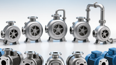
Choosing industrial centrifugal pumps is not a matter of matching a pipe size or selecting the largest motor. The right choice depends on the duty point: required flow, total head, fluid properties, and how the system actually operates. Pump engineer and author Igor J. Karassik’s work supports a useful principle, paraphrased here: “Choose for the system, not the catalog.” That distinction matters.
Start with measured conditions. Record the flow range, suction pressure, temperature, and any solids or corrosive components. Then compare the system curve with the pump curve, rather than relying on a single catalog rating. Check that the operating point stays near the pump’s preferred efficiency region. Review net positive suction head requirements, too; a noisy pump, vibration, or a damaged impeller may point to a suction problem. Small details count.
Materials need equal care. A seal or casing that suits clean water may fail with a hot, abrasive process fluid. Consider motor load, control method, maintenance access, spare parts, and expected run hours. These choices affect energy use and downtime over the pump’s service life. Experienced teams still make imperfect estimates, especially when demand changes by season. That is worth revisiting. Confirm assumptions with operating data, and ask a qualified pump specialist to review the selection before purchase. A sound choice is specific to the installation—not just persuasive on paper.

Choosing an industrial centrifugal pump starts with the duty point, not the largest flow number on a process sheet. Define the required flow rate and note whether it is steady, intermittent, or likely to change. A wash line may demand a brief peak that differs sharply from normal operation. Small details matter. Check the flow units and measurement basis; confusing gallons per minute with cubic metres per hour can distort the selection.
Calculate total dynamic head at the required flow. Include elevation change, pressure differences between vessels, and friction losses through pipes, valves, filters, and fittings. Use the actual pipe route where possible. A long, narrow line can require much more head than a simple layout suggests. Do not guess. Early estimates are often wrong, and a neat calculation can still miss a partly closed valve or a future filter.
Describe the fluid at operating temperature, not just by its name. Record density, viscosity, solids size and concentration, and any corrosive or abrasive qualities. A thick liquid can reduce centrifugal-pump performance, while suspended grit may accelerate wear. Temperature also affects viscosity and vapor pressure, so check whether adequate suction conditions are available. If properties are uncertain, state the assumptions and verify them before final selection. That step is easy to postpone—and often regretted.
A centrifugal pump should be selected around the duty point: the required flow and head where the system normally operates. Plot that point on the manufacturer’s curve, then check how close it sits to the best efficiency point (BEP). Hydraulic Institute guidance in ANSI/HI 9.6.3 treats preferred operating regions as dependent on pump design and specific speed; one fixed “safe” percentage does not fit every pump. The curve is not the whole story. Confirm the system curve, liquid properties, impeller diameter, and expected operating range. A valve that is routinely throttled may hide a poor match.
The U.S. Department of Energy’s Improving Pumping System Performance sourcebook reports that pumping systems use nearly 20% of global electricity demand and 25–50% of energy in some industrial operations. That makes a close duty-point match worth checking carefully. Near BEP, hydraulic loading and internal recirculation are generally reduced, which can limit vibration and wear. For a practical check, compare the normal duty point with minimum and peak demand, then review motor load and NPSH margin. A pump chosen only for peak flow may run far from BEP most days. It happens. Field readings can also differ from design estimates, so leave room to question the original assumptions.
For an industrial centrifugal pump, NPSH is a suction-side pressure check, not just a paperwork figure. Available NPSH (NPSHa) describes what the system supplies at the pump inlet. Required NPSH (NPSHr) is the minimum stated in pump performance data for a specified flow. Keep the terms distinct. NPSHr does not include a safety allowance for every installation.
Compare NPSHa and NPSHr at the actual flow, fluid temperature, and pump speed. Calculate NPSHa from absolute inlet pressure, liquid level or static head, and vapor pressure. Include losses in pipes, elbows, valves, and strainers. Warm liquid, a falling tank level, or a partly blocked strainer can shrink the margin. Keep units consistent. A barely positive difference may not be enough; follow engineering guidance and the pump supplier’s recommended margin.
A pump may cavitate only during hot afternoons or near the end of a tank drawdown. Listen for a gravel-like sound and watch for unstable flow, but do not rely on symptoms instead of calculation. Check the suction line for air leaks and unexpected restrictions. The curve is useful. The installation still needs a site check. If operating conditions change, recalculate NPSHa before accepting the new duty point.
For an industrial centrifugal pump, match wetted materials to the actual fluid, not just its name. Check concentration, temperature, pH, solids, and cleaning chemicals. A stainless-steel grade may handle a mild aqueous process but pit in warm chloride service. Abrasive particles can also wear casing surfaces and shorten seal life. NACE International’s 2016 IMPACT study estimated global corrosion costs at US$2.5 trillion annually, or 3.4% of global GDP. That figure is economy-wide, not pump-specific, but it shows why corrosion resistance deserves serious attention.
Choose seal faces and elastomers for both the fluid and operating conditions. Consider dry running, pressure changes, temperature swings, and whether the liquid can crystallize or carry fine solids. A seal compatible at room temperature may swell or harden when hot. Not always obvious. For hazardous or valuable fluids, ask a qualified pump or seal engineer to review containment needs and applicable standards, such as API 682 where relevant. Confirm selections against the manufacturer’s material compatibility data; charts are useful, but they cannot capture every mixture.
Tips: Share the fluid’s full composition and normal, startup, and cleaning temperatures with the supplier. Ask for the proposed casing, impeller, shaft, seal faces, and elastomer materials in writing. If the chemistry is uncertain, test a sample. That extra step can feel slow, and sometimes the data remain incomplete. Better to record that uncertainty than to assume.
| Fluid and Service | Typical Operating Concerns | Casing Material to Evaluate | Impeller and Wetted Parts to Evaluate | Seal Arrangement to Consider | Selection Checks |
|---|---|---|---|---|---|
| Clean, near-neutral water at ambient temperature | Corrosion, water quality, operating pressure, and occasional dry running | Cast iron for many general-service duties; stainless steel where water chemistry or cleanliness requires it | Bronze, cast iron, or stainless steel, selected to suit the casing, water chemistry, and wear requirements | Single mechanical seal with elastomer and face materials compatible with the water and temperature | Check chloride content, pH, temperature, solids, suction conditions, and any potable-water requirements |
| Seawater or chloride-bearing water | Pitting and crevice corrosion, especially at stagnant zones, joints, and deposits | Duplex stainless steel or another seawater-qualified alloy; standard stainless grades may be unsuitable in some conditions | Use a compatible corrosion-resistant alloy for the impeller, shaft sleeve, and other wetted parts | Single or double mechanical seal, with faces and elastomers selected for the water chemistry and leakage requirements | Confirm chloride level, temperature, velocity, oxygenation, crevice exposure, and the alloy supplier’s corrosion data |
| Mildly corrosive process water or dilute chemical solution | Corrosion rate can change significantly with concentration, temperature, and contamination | Stainless steel or a higher-alloy material only after checking the exact chemical conditions | Match all wetted components to the same compatibility assessment; do not assume the impeller has the same corrosion exposure as the casing | Single mechanical seal for controlled, non-hazardous service; consider a containment or double-seal arrangement where leakage risk warrants it | Use the exact chemical name, concentration, temperature, and impurity profile when consulting compatibility data |
| Hydrocarbon liquids, such as refined fuels or lubricating oils | Flammability, vapor pressure, temperature, viscosity, and leakage control | Carbon steel or stainless steel, subject to corrosion allowance and process specifications | Carbon steel, stainless steel, or another compatible alloy; consider erosion and solids if present | Mechanical seal selected for the liquid’s lubricity, vapor pressure, temperature, and emissions requirements | Check hazardous-area requirements, seal support plan, static electricity controls, and applicable process standards |
| Hot water or condensate | High temperature, flashing, thermal expansion, and reduced seal-face lubrication | Cast iron or steel for suitable duties; stainless steel where chemistry or system requirements call for it | Materials compatible with the water chemistry and operating temperature | High-temperature mechanical seal with suitable faces, secondary seals, and a seal chamber arrangement | Check temperature at the seal chamber, suction pressure, vapor pressure, thermal shock, and minimum flow |
| Water containing sand or other abrasive solids | Abrasive wear, blockage, erosion, and damage to seal faces | Wear-resistant cast iron, steel, or a suitable alloy, depending on particle size and impact conditions | Wear-resistant material or a replaceable wear design; consider an impeller suited to the solids size and concentration | Heavy-duty seal with an appropriate flush or barrier arrangement where needed; packing may be considered for some services | Specify solids concentration, particle size and hardness, flow range, flushing-water quality, and wear-part maintenance access |
| Slurry with suspended process solids | Settling, abrasion, erosion, changing viscosity, and possible plugging | Material selected for both corrosion and erosion; lining or specialized construction may be appropriate | Slurry-duty impeller and casing geometry; evaluate hard materials or replaceable liners where service data supports them | Seal arrangement designed for solids exclusion and reliable flushing; consider a double seal for critical leakage control | Provide solids loading, particle distribution, density, rheology, settling tendency, and expected operating range |
| Viscous liquid, such as heavy oil or syrup | Higher friction losses, reduced pump efficiency, and increased starting torque | Carbon steel, stainless steel, or another compatible material based on chemical and temperature conditions | Compatible wetted materials; verify impeller clearances and suitability for the actual viscosity | Mechanical seal selected for viscosity, temperature, and face lubrication; confirm seal chamber circulation | Use viscosity at operating temperature, not only at room temperature; verify pump performance corrections and motor sizing |
| Toxic, highly hazardous, or environmentally regulated liquid | Personnel exposure, emissions, and consequences of primary-seal leakage | All wetted materials must be verified against the liquid and governing safety requirements | Include shaft, sleeves, fasteners exposed to the fluid, and auxiliary piping in the compatibility review | Consider a pressurized dual mechanical seal or another engineered containment system with suitable monitoring | Define allowable leakage, containment strategy, monitoring, emergency response, and applicable regulations |
Selection note: These are preliminary material and seal options, not universal specifications. Confirm compatibility using the exact fluid composition, concentration, temperature, pressure, solids content, and operating conditions. Review the final selection with the pump and seal manufacturers and applicable engineering standards.
Apply Affinity Laws at Constant Impeller Diameter: Q∝N, H∝N², P∝N³
At a fixed impeller diameter, pump speed links flow, head, and power through the affinity laws. If speed changes from N1 to N2, estimated flow changes in the same ratio: Q2/Q1 = N2/N1. Head follows the square of that ratio, while absorbed power follows its cube.
A 10% speed increase suggests about 10% more flow, 21% more head, and 33% more power.
That is not small. The cubic rise in power can push a motor toward its limit, even when the flow increase looks modest.
Treat these figures as estimates, not guaranteed operating results. They assume comparable fluid conditions and pump efficiency; actual flow depends on where the pump curve meets the system curve.
During a speed adjustment, record suction and discharge pressure, flow, motor current, and vibration. Check the manufacturer’s curve and motor rating before raising speed, and watch for cavitation or unstable operation.
A pressure gauge may show more head, but it cannot confirm adequate flow by itself. It is easy to treat a small speed change as harmless. I would recheck the measurements under steady conditions, because real systems rarely behave as neatly as the equations.