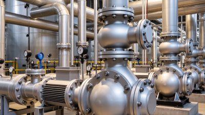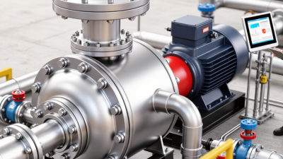
A high pressure pump moves liquid by adding energy until the fluid reaches the pressure required by a process. That pressure may drive water through a narrow nozzle, feed a cleaning system, or overcome resistance in industrial piping. The principle sounds simple. Selecting the right pump is not.
The U.S. Department of Energy’s Improving Pumping System Performance sourcebook reports that pumping systems use nearly 20% of global electricity and can account for 25% to 50% of energy use in some industrial operations. These figures cover pumping systems broadly, not high-pressure pumps alone. Still, they show why pressure, flow rate, efficiency, and operating conditions deserve careful attention. A pump’s nameplate rating cannot tell the whole story. Real performance depends on the fluid, pipework, controls, and maintenance.
This guide explains what defines a high pressure pump, how it works, and where engineers use it. It also examines common pump types, key selection factors, and practical maintenance checks. Small details matter: a worn seal, a clogged inlet, or an undersized pipe can change performance and raise operating costs. That distinction is easy to miss.
No named expert quotation is included here because no verifiable source was provided. Adding an unverified quote would weaken the article’s reliability. For a publishable expert citation, use a traceable interview, technical paper, or statement from a qualified pump engineer.
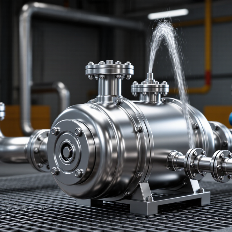
A high-pressure pump is a mechanical device that moves liquid while creating pressure above what a standard transfer pump typically provides. It draws fluid through an inlet and pushes it through an outlet, using a motor or engine to drive its pumping mechanism. The exact pressure range depends on the pump design and application. The name can be misleading. Pressure is only one part of its performance; flow rate and fluid compatibility matter too.
Its purpose is to deliver water or another suitable liquid where ordinary pressure is not enough. In cleaning systems, for example, a narrow nozzle can turn pressurized water into a focused jet for removing grime from hard surfaces. In industrial processes, pumps may feed liquid through pipes, filters, or equipment that needs a steady supply. Fit matters. A pump selected without considering temperature, viscosity, or required flow may wear quickly or perform poorly. Operators should check the manufacturer’s specifications and inspect seals and connections for leaks. Small details count. Even a sound pump can disappoint when its inlet is restricted or its pressure setting is unsuitable. There is no single best model for every job.
A high-pressure pump moves a liquid while raising it to pressures needed for tasks such as reverse osmosis, pressure washing, hydroblasting, and waterjet cutting. The ranges below are representative; actual operating pressures depend on equipment and application.
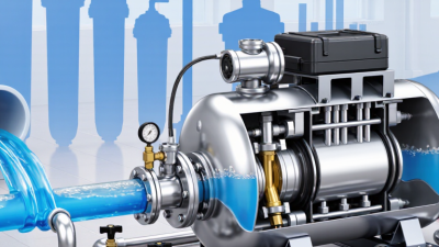
A high-pressure pump moves liquid against resistance; it does not simply create pressure in isolation. In a positive-displacement pump, a piston traps a small volume, then pushes it through an outlet check valve. Each stroke adds fluid to the line, raising pressure until it meets downstream resistance or a control valve opens. Picture a steel plunger advancing and a discharge hose giving a slight pulse. Not magic. In a centrifugal pump, an impeller accelerates liquid outward. A diffuser or volute then slows the flow, converting some of its velocity into static pressure. The mechanisms differ, but both depend on flow, system resistance, and pump design.
A pump’s maximum pressure is not necessarily its normal operating pressure. Flow can fall as resistance rises, so seals, piping, and relief devices must match the actual duty. The U.S. Department of Energy’s Improving Pumping System Performance: A Sourcebook for Industry reports that pumping systems use nearly 20% of global electricity and 25–50% of electricity in some industrial facilities. That scale matters. Check pressure and flow under real operating conditions, and watch for pulsation or heat. One caveat: those figures describe pumping systems broadly, not high-pressure pumps alone. Looking only at the gauge can be misleading; the pump curve and the whole line matter too.
A high-pressure pump converts mechanical energy into pressurized fluid flow. Its drive may be an electric motor or engine, while the pump head directs fluid through working chambers. Inside, pistons or plungers move back and forth, drawing fluid in and forcing it out. The exact design varies, but the basic job stays similar. Small parts matter.
Inlet and outlet valves control flow direction. Their seats must seal properly; grit or wear can cause pressure loss and uneven operation. Seals keep fluid from escaping around moving parts, though they wear over time and need inspection. A filter can catch debris before it reaches sensitive components. On many systems, a pressure regulator or unloader limits pressure or redirects flow when demand changes. A gauge helps operators monitor the reading, but it cannot reveal every fault. A steady needle may hide a worn seal or restricted inlet. That distinction matters. Check connections, fluid condition, and unusual vibration during routine maintenance, and follow the pump’s specified operating limits.
| Component | Primary Function | How It Works | Key Operating Consideration |
|---|---|---|---|
| Pump casing or head | Contains the pumped liquid and provides structural support for internal components. | Forms the pressure boundary and directs liquid through the pump’s internal flow passages. | Material and pressure rating must suit the liquid, operating pressure, and temperature. |
| Plunger, piston, or diaphragm | Creates the displacement that moves liquid and raises its pressure in a reciprocating pump. | A drive mechanism moves the pumping element back and forth; inlet and discharge valves control the flow direction. | Seals and wetted materials must be compatible with the liquid and required duty cycle. |
| Inlet and discharge check valves | Control one-way flow into and out of the pumping chamber. | The inlet valve opens as chamber pressure falls; the discharge valve opens when chamber pressure exceeds outlet pressure. | Debris, wear, or incorrect valve seating can reduce flow and cause pressure fluctuations. |
| Drive mechanism | Transfers power from the motor or engine to the pumping element. | A crankshaft, connecting rod, or other transmission converts rotary motion into reciprocating motion in many positive-displacement pumps. | Alignment, lubrication, and operating speed affect vibration, wear, and service life. |
| Shaft seal or packing | Limits leakage where a rotating or moving shaft passes through the pump housing. | A mechanical seal or packing arrangement creates a barrier between the pumped liquid and the surrounding environment. | Some designs require controlled lubrication or cooling; leakage should be monitored according to the pump design. |
| Pressure relief valve | Helps protect the pump and connected system from excessive pressure. | Opens at a preset pressure to divert or release flow, depending on the system configuration. | It should be correctly selected, set, and routed; it is not a substitute for operating within equipment limits. |
| Inlet strainer or filter | Captures particles that could damage valves, seals, or other internal parts. | Liquid passes through a screen or filter element before entering the pump. | A blocked or undersized filter can restrict inlet flow and contribute to cavitation or reduced performance. |
| Pressure gauge or sensor | Indicates or measures pressure at a selected point in the system. | A gauge displays pressure locally; a sensor can send a signal to a control or monitoring system. | Use an appropriate range and location, and verify instrument accuracy as required. |
| Inlet and discharge connections | Provide the interfaces between the pump and the piping system. | The inlet supplies liquid to the pump, while the discharge carries pressurized liquid to the system. | Correct sizing and secure connections help limit restrictions, leaks, and unwanted vibration. |
High-pressure pumps are designed to move liquid against substantial resistance. Their designs vary, and the right choice depends on pressure, flow rate, fluid properties, and operating time. Pressure is only part. A pump that reaches the required pressure may still deliver too little flow for the job.
Plunger pumps are a common positive-displacement type. A moving plunger pushes a measured volume through the outlet, making these pumps suitable for high pressure and relatively controlled flow. Their discharge can pulse, so some systems use a dampener. Seals and valves also need regular inspection, especially when the liquid contains particles.
Multistage centrifugal pumps build pressure as liquid passes through several impellers. They generally provide smoother flow than reciprocating designs, but performance depends on correct sizing and operating conditions.
Diaphragm pumps move liquid by flexing a membrane, which separates the fluid from some moving components. This can be useful for metering or handling fluids that require isolation, though material compatibility matters.
Details matter.
In practice, temperature, viscosity, and maintenance access can change which type works best. A tidy comparison table cannot capture every installation; checking the pump curve and the actual fluid conditions is a sensible step.
A high-pressure pump moves liquid against substantial resistance while maintaining the flow a process needs. It may serve reverse-osmosis systems, boiler-feed circuits, industrial washing, or waterjet cutting. The right choice depends on the job, not pressure alone.
Start with required pressure and flow, then check whether both must remain steady during changing demand. A pump sized for peak pressure can waste energy when the system usually runs below that point. The U.S. Department of Energy’s Improving Pumping System Performance: A Sourcebook for Industry reports that pumping systems use nearly 20% of global electricity demand, and can account for 25–50% of energy use in some industrial operations. Efficiency deserves attention.
Fluid details matter. Temperature, viscosity, solids, and chemical compatibility affect pump materials, seals, and wear. Check inlet conditions and net positive suction head to reduce cavitation risk; a rattling pump is not a useful warning system. Also consider pulsation, noise, maintenance access, and available space. That matters. A technically suitable pump may still be a poor fit if seals are difficult to service or controls cannot match the process. Leave room for real operating variation, because specifications rarely capture every awkward detail on site.